Z80 Information
20 Jan 2013
Six or seven years ago, I bought a box full of fun stuff on eBay. It turned out to include a few Z80 processors. I had just finished my army duty and still remembered the math and physics lectures from college (equivalent) where most of the time had been wasted playing Super Mario on our Texas Instruments TI83+ graphing calculators who run on the very same processor. So I was well aware on what wonders it's capable of. Unfortunately, I didn't even have time to start playing with my new goodies before I went to university and my life turned into a mess.
The time finally came about a year and a half ago. I was having the first vacation of my life and actually had time to spare.
At this point I had no kind of plan. So I started out by trying to find out if at least one of the Z80s actually worked.
History of the Z80
According to Wikipedia, the Z80 processor was launched in 1976 by Zilog. The founder of Zilog had previously worked for Intel on their 8080 microprocessor. The Z80 is therefore designed to run any code which runs on the former.
Further, the Z80 features an extended instruction set compared to the 8080. The extra instructions include bit and block operations. The Z80 also has two sets of registers which can be swapped through a special register, indexed addressing and vectorized interrupts.
I have no experience working with the 8080 and this far only a little bit of actually programming a Z80. I've already, however, begun to appreciate some of those features.
What I appreciate even more - at least this far - is the following hardware features of the Z80 compared to the 8080.
- A single 5V power supply - as opposed to +5V, -5V and +12V for the 8080
- A single clock signal input - as opposed to two for the 8080
What this means
What those hardware features mean, is that getting a Z80 to run is actually really simple. All we need in ways of support circuits are a single square wave clock signal and a reliable reset circuit. Oh, and a power supply of course.
A step back
But we shouldn't get ahead of ourselves here. Let's instead take a step back and look at the Z80.
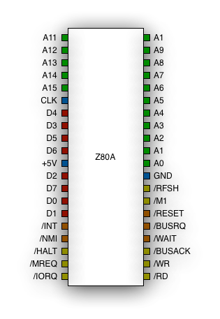 This is the pinout of a standard Z80 in a 40-pin DIP package. I have
colorized the pins to show one way of grouping their functions.
This is the pinout of a standard Z80 in a 40-pin DIP package. I have
colorized the pins to show one way of grouping their functions.
A line above the pin name or a / before it (such as /INT) indicates
that the pin is Active Low, i.e. 0V means yes and 5V means no in layman
terms.
Green
The green pins are the address bus. A0 to A15 are used to indicate an address in memory during a memory read or write operation. A0 to A7 are also used to select I/O device during a port read or write operation. The address bus is output only.
Red
The red pins are the data bus. D0 to D7 are used to transfer or receive data during a memory or port read or write operation. The data bus can also be used to indicate which device fired an interrupt. The data bus can be both input and output.
Blue
The blue pins are what keeps the Z80 going. The 5V DC power supply, a ground connection and a clock signal. We'll look more on the clock signal later.
Orange
The orange pins are used to control the Z80.
/INTindicates that a hardware interrupt occurred and makes the Z80 act on this./NMIis a Non Maskable Interrupt and has higher priority than theINT/WAITcan be used by memory or I/O devices to make the Z80 wait during a read or write operation while the device prepares to fill the request./BUSRQis used by external devices to request control over the data, address and system control buses. When the Z80 is ready to hand over control, this is signaled to the requesting device via theBUSACKpin./RESETis used to reset the Z80 into a well defined state.
All orange pins are input only.
Yellow
The yellow pins are used to control peripherals and other parts of the computer system.
/HALTindicates that the Z80 is in a halted state, i.e. it is waiting for an interrupt to happen./MREQindicates that the Z80 wishes to access memory./IORQindicates that the Z80 wishes to access an I/O port./RDgoes low during a memory or I/O read operation./WRgoes low during a memory or I/O write operation./BUSACKindicates that the Z80 has let an other device take control of the buses./M1indicates that the Z80 is fetching the next instruction from memory. This pin turned out to be incredibly useful for debugging./RFSHback in the days memory circuits couldn't keep their contents indefinitely, even with power on, but had to be given a refresh pulse every now and then. This usually required some extra circuitry which kept track of which memory addresses needed refreshing when. The Z80, however, outputs a refresh signal from time to time and also gives an address to refresh at A0 to A6(!).
All yellow pins are output only.
Fetch Decode Execute
A CPU operates in what's called instruction cycles. The instruction cycles can be broken down into three sub-cycles, namely the Fetch cycle, the Decode cycle and the Execute cycle.
During the Fetch cycle, the processor reads an instruction from memory. It keeps the address of the next instruction to read stored in a special register, the Program Counter PC. The Z80 also outputs the refresh signal during the end of the Fetch cycle. After reading an instruction PC in incremented by one.
During the Decode cycle, the processor decodes the read instruction. If more data needs to be read from memory (e.g. an address in a jump instruction) it is read now (PC is incremented accordingly).
During the execute cycle, the processor does what the instruction told it to. It might for example - in the case of a jump instruction - change the contents of the PC register, or add two registers together.
The cycle then repeats indefinitely or until the processor is halted.
The simplest instruction
So... the goal of this post was to make a Z80 tester, right? Actually, that will probably have to wait for the next post, because this one is getting really long now. However, it makes sense to look at one last piece of information right now. To make sure a Z80 is working, we'd want it to go through a number of instruction cycles. As a first step, though, we don't actually need it to do anything, but just move on to the next instruction.
Luckily, there's an instruction for this.
From the Z80 CPU Users Manual by Zilog:
NOP
Description: The CPU performs no operation during this machine cycle.
Sounds just like what we need! To make it even more perfect, the nop
instruction is indicated by the byte 0x00 or all zeroes.
I'll let you think about the implications of this until next time.